Vcore issue?

archer21

Member
I noticed that there is a motherboard Vcore and a CPU Vcore section under HWinfo and was curious as which one is the actually Vcore:
forum_zpst5ygf1lp.png

forum%202_zpsxubgkqsz.png


The ones under the motherboard section seem incorrect to me. Is this right and normal?
I am running stock voltages(Bios voltage settings on Auto) at the moment with XMP enabled (i7 4790K @ 4.4ghz on all cores and RAM at 1600mhz dual channel).
Which voltage are the cores actually getting?
 
This has been discussed several times here - VID is not the measured Vcore, but the voltage the CPU requests (and thinks it gets). Some mainboards might apply certain offsets to VID, so the CPU might in fact be getting a different Vcore.
However for Haswell-based CPUs (which feature the FIVR), there are usually problems monitoring the real Vcore, especially in idle. Thus some mainboards report VID as Vcore, which is also not quite correct.
 
I had just ran an ASUS ROG Realbench stress test before taking the screenshot.
So which value should I go by? Is the CPU right or the board right? Based on what you said, the board is "right" and is applying excessive voltage to the CPU
I'd rather it not be pushing over 1.25 volts at load.
 
Under load I think the mainboard Vcore value should be more accurate.
However since those values are ASUS-proprietary and they don't tell us how accurate they are, I'd suggest to confirm this with ASUS own tools (though I believe they should match HWiNFO).
 
archer21

I do not see any obvious errors circuitry. In this case, the power control circuit CPU put on a bus value of the input voltage of individual voltage regulator cores needed at any given time for their work, but as a temporary model of behavior of the switching regulator is similar to integrating a chain, that in time we can see the difference between the exposed currently VID and the output voltage VRM, and since the board uses a digital VRM, the output voltage has a step change in nature.
 
I checked HWINFOs data with ASUS AI Suite 3s data and it's consistent. However oddly enough AI Suite reports VCCIN as 1.232..which would be the VID across all monitoring programs I've used including AIDA64 and CPU-Z.

Why is the motherboard applying that much voltage(1.248-1.264) when all the CPU is requesting is 1.228-1.24?
 
Sorry, but I cannot answer that question. Check you CPU voltage configuration (adaptive/override) and whether there's an offset set.
You might also check with ASUS support...
 
archer21

1) The only objective method of controlling operation modes of electrical systems is the measurement of their parameters using the last metrological verification of measuring instruments. Built-in device hardware and software control of their settings are intended only to indicate a fault and can be of any metrological error.

2) Acceptable for the normal operation of the device or individual node range of supply voltages and temperatures indicated in the technical documentation to them, and at the exit of these parameters exceed the limits device performance can not be guaranteed until sudden failure.

Documentation and at least information on the recommended and maximum permissible operating conditions can be found on the device manufacturer, and if you did not find them there, then consult a tech support department specialists or engineers your nearest manufacturer's service center.

Admission to these parameters is laid in the scheme in their design is not so great to arbitrarily change the mode of the device, but it is sufficient to account for the spread of technological parameters of their elements.

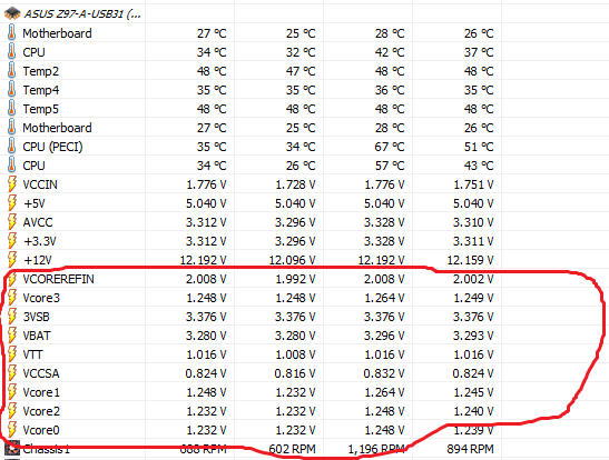
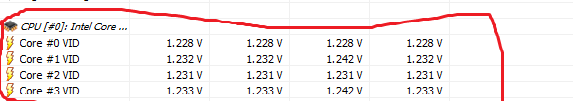
3) With regard to the reliability of measurement CPU-Z, AIDA64 programs, with respect to CPU-Z please tell me how a Core 2 Duo E8500 runs with frequent bus and 333 MHz (multiplier of 6.0 - 9.5) can operate at a clock frequency of 6.8 GHz? :) And such "measurements" in their base a good 80% - 90%.

The same is true of AIDA64 - its authors used measurement technique has not been formally guarantee reproducible results and, in many cases, the testimony of the program differ from the data of devices in a few times.

This information programs designed to give a general idea about the device and more of them require pointless, and as reader hardware monitoring sensors, then CPU-Z certainly believe it is necessary because it reads the value of the VID (really do not know what), and rightly so: ), and 4.5 Decade digital voltmeter double integration accuracy class of 0.01 on the same card can not be trusted because its measurements differ from the readings of standard programs. :)
 
Martin, I have attached an image of my BIOS voltage settings for your review. It would seem it is indeed applying an offset, and I am personally unfamiliar with offsets, as I have only ever dealt with manual Vcore and baseclock.

Victor, thanks for the helpful info I understand 70% of it :)


What do you think?
 
I don't see any Vcore offset applied there. The one you highlighted is for the CPU System Agent.
 
Martin said:
I don't see any Vcore offset applied there. The one you highlighted is for the CPU System Agent.

Ah ok, I'm not sure what offsets are what. As I said, I have no experience with offsets. Which offset would I be looking for?
 
The one for Core Voltage.
You might also check in the main HWiNFO window which lists all hardware components, under CPU what overclocking parameters including offsets are used.
Note, if you're using Sensors-only mode you'll need to deactivate it, because the main window is not shown in Sensors-only mode.
 
archer21

Hint - the position of the operating point of the current-voltage characteristics of the transistor thing is very nonlinear and depends on the operating frequency and output impedance, and on its temperature, while the field-effect transistor, unlike the bipolar transistor the steepness of the current-voltage characteristics (S) and unity gain frequency (Uout/Uin (f)=1) as that of radio tube to which it is similar in its frequency and amplifying properties with temperature are sharply reduced. It protects against thermal breakdown, but a bipolar transistor with temperature increasing current gain (h21e) and several rises unity gain frequency, but it is prone to thermal runaway avalanche, and the field does not have this drawback.

And at the same time released in the process of switching the thermal power transistor (when the switch is closed - in cutoff its heating can be practically neglected, and when it is open, its resistance is so small that it is heated to hundreds of times smaller than the switching process when the transistor is active mode) is proportional to the square of the frequency ratio, so that even a slight increase in the operating frequency of the transistor can dramatically increase the heat and at some point it just will not be able to switch to the selected frequency.
 
Back
Top